[1] ![]() ,
,
where Pv = vapor pressure of H2O in air (Pa), and Ps = saturation vapor pressure of H2O in air (Pa).
This laboratory was written for a graduate-level class in soil physics. Don't let that scare you; grad students don't do this work any better than you do. There is nothing here that anyone with a good background in algebra and the ability to use a computer spreadsheet can't handle. It does help, though, to have some knowledge of electrical or electronic circuits. Nevertheless, it is a challenging assignment that will take some persistence to finish.
This lab will lead the student through the math and electronic circuits needed to design and possibly build a thermistor psychrometer with fan aspiration. Most of the psychrometer elements themselves, with the exception of the thermistors, are common hardware and plumbing parts. Several pieces of complex hardware are needed, including a Campbell Scientifice, Inc. 21X datalogger, a temperature-controlled water bath with a range of at least -10 to 50 °C, and a platinum resistance thermometer and bridge circuit, suitable for connection to the CSI datalogger.
A psychrometer is a meteorological instrument used to determine relative humidity, rh [1], the measure by vapor pressure of how much water is in the air compared to how much it could hold before precipitating out. It can be as simple as a sling psychrometer, consisting of two mercury thermometers, one with a bare bulb, and another with a bulb covered with a wick wetted with distilled water. It's call a sling psychrometer because to get the reading, one literally slings it in a circle about one's head, using the resulting draft to make the thermometers come rapidly to accurate readings.
[1] ![]() ,
,
where Pv = vapor pressure of H2O in air (Pa), and Ps = saturation vapor pressure of H2O in air (Pa).
For relative humidity less than 100% water evaporates from the wetted thermometer, cooling it to the wet bulb temperature, Twb (° K). This makes the reading is lower than the dry thermometer, or dry bulb temperature, T (° K). The drier the air, the larger the depression of Twb from T. Barometric air pressure, pa (Pa), also has an effect. From these three measurements, Pv and Ps can be calculated, giving rh.
We will be using a slightly more complicated device, called an aspirated psychrometer, designed for unattended operation in the field. It has a water reservoir and a 12 VDC electric fan to generate the draft. Instead of mercury thermometers, it uses temperature sensitive resistors, called thermistors, to measure temperature electronically. It uses ordinary PVC plumbing pipe to house the thermistors and the fan, to channel the air properly over the thermistors, and to hold intake and outflow filters to reduce interference from dust and insects.
This is a multi-purpose lab intended to teach a range of skills necessary for you to understand how to design a psychrometer, calibrate it, and process the data it provides to get relative humidity. It does not cover, however, such things as the mechanical, carpentry and electronic soldering skills needed to build every part. It will, however, require you to learn a little more about electronic circuits and the math necessary to predict their operation.
In order, we will cover these topics:
1) What is a thermistor and how does it work?
2) How do we use a thermistor in a resistance bridge?
3) How do we calibrate a thermistor in a resistance bridge?
4) How do we build a thermistor psychrometer?
5) How do we take data from a psychrometer using a datalogger?
6) How do we change the raw measurements into relative humidity?
Some of the concepts will be difficult to understand for the first time. But they will be presented in a mostly cook-book manner. If you persist in trying to master them, you will have the beginnings of the ability to design and make your own instrument out of common materials and electronic components. If you should acquire common technical skills in mechanical and electronic construction elsewhere, there is no question that such instruments will be less intimidating to you in the future. Good luck.
What is a thermistor and how does it work?
Along with this laboratory assignment, you should have received a 1.44 Mb floppy disk in IBM format, entitled "NTC Thermistor". To read it, you will need a PC with a browser and a copy of Adobe Acrobat Reader 3.0. If you do not have Acrobat Reader, you can download it for free from http://www.adobe.com. Acrobat Reader works best if it is listed in the browser preferences as the helper application for *.pdf files. You can print out files from Reader, if needed.
The floppy is a modified set of html pages and pdf files from the web site of Thermometrics, Inc.: http://www.thermometrics.com. It contains a lot of information on negative temperature coefficient (NTC) thermistors to bolster the information given here. You should begin by opening the page whatis.html in your browser and reading it, then follow the links.
As the material notes, an NTC thermistor is a temperature-sensitive resistor, often made of semi-conducting metal oxides. Its resistance goes down as temperature increases. The simplest equation for this is [2], relating the temperature of the thermistor, T, to the thermistor resistance, Rt. If a reference temperature, To, is specified, for which the thermistor resistance is Ro, then [2] can be written as [3]. These equations are only approximations. They can be off by as much as 0.3 ° K over a span of 50 ° K. Equation [4] is more accurate, good to better than 0.001 ° K.
[2] ![]() ,
,
where Rt = thermistor resistance (W), a and b are calibration constants, and T = temperature of the thermistor (° K).
[3] ![]()
[4] ![]() , where Ai, i = 1,3, are calibrations constants.
, where Ai, i = 1,3, are calibrations constants.
Consider now an NTC thermistor, Keystone Thermometrics model RL0504-27.76K-120-G120-G1. According to company data, it has a resistance of Ro = 50 kW at 25 ° C (To = 298.15° K), a temperature coefficient, a = -0.0477 W/W/° K, a dissipation constant of 0.75 mW/° K and time constant of 16s in still air. Let us suppose that it has a maximum power dissipation of 0.05 mW. What do these numbers tell us?
The specified resistance at 25 ° C gives us Ro and To for equation [3]. For those who don't know, one ohm (W) is the resistance to electrical current through which a voltage of one volt (V) will produce a current of one amp (A), according to Ohms' law [5]. The temperature coefficient, a, is related to b by the equation [6]. Since a is defined at To, [6] reduces to [7], which gives b = 4240.2. Figure 1 shows the resulting temperature-resistance curve.
[5] ![]() , where E is voltage (V) across the resistance,
R (W), and I is the current (A) through
the resistance or resistor.
, where E is voltage (V) across the resistance,
R (W), and I is the current (A) through
the resistance or resistor.
[6] ![]()
[7] ![]()
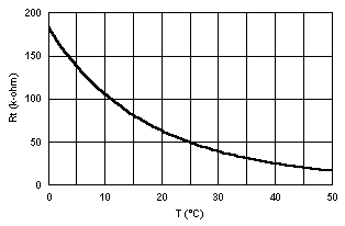 Figure 1:
Approximate Temperature-Resistance Curve for RL-0504-27.76K-120-G120-G1
thermistor with To = 298.15 ° K, Ro = 50 kW and b = 4240.2 Figure 1:
Approximate Temperature-Resistance Curve for RL-0504-27.76K-120-G120-G1
thermistor with To = 298.15 ° K, Ro = 50 kW and b = 4240.2 |
The maximum dissipation is the most electrical power that can be dissipated in the thermistor, by passing current through it, without permanently changing its electrical characteristics, or causing it to burn out. The unit of electrical power, P, is the watt (W), according to any of the three forms in equation [8]. For example, if one places a voltage of 2 V across the thermistor, when the temperature of the thermistor is 298.15 ° K (25 ° C), which means then the power dissipated in the thermistor is Pt = (2V)2/(50000 W) = 0.08 mW. So, even this small value of voltage across the thermistor is likely to burn it out. In fact, if one connected 2 V across this thermistor in air at 25 ° C, it is possible that the heating would lower the thermistor resistance, increasing the power dissipated in a vicious cycle until it's toast.
[8] ![]()
The dissipation constant, 0.75 mW/° C, gives us the rate at which the thermistor increases in temperature above the ambient temperature, according to the power generated in it by electrical current. This is called self-heating. These values are typically given for still air. Another medium or moving air will change the rate at which the thermistor loses excess heat to its surroundings, thus changing the constant. We use it here as a rough indication the maximum power we can afford to generate in the thermistor and maintain a given measurement error.
If we should want a measurement error due to self-heating on the order of 0.001 ° C, then the maximum power we can dissipate in the thermistor is 0.00075 mW. At a resistance of 50,000 W, this means a maximum voltage of 193.6 mV across the thermistor, according to [8]. Let's say that we wish to measure across a range of 0 to 50 ° C. Equation [3] and Figure 1 tell us that range of resistances will be from 183,756.7 W to 16,640.56 W, respectively. For a maximum self-heating error of 0.00075 mW, this means that the maximum allowed voltage across the thermistor can vary from 371.2 mV to 111.7 mV, respectively.