How do we use a themistor in a resistance bridge?
Now consider the simple resistive voltage divider in Figure 2. An ideal voltage source is represented by a circle with the strength, Vs (V), inside, with indications of the positive, +, and negative, -, terminals. An ideal voltage source has no internal resistance, like a perfect battery, and has a fixed voltage. The thermistor is shown as a resistor in a circle with the designation, Rt. It is connected to the positive terminal of Vs with a fixed resistor, R, and directly to the negative terminal. The voltage across the thermistor, Vt, can be calculated by the voltage divider formula [9].
 |
[9] ![]()
This is called a resistance bridge. In particular, it is a type of 3-wire bridge because it requires only three wires to make the measurement - the positive connection to the source, Vs, the negative connection to the source, and the positive return from the thermistor voltage, Vt. Notice how Vs and Vt are connected in common at the negative ends. This is often called the common or reference or ground potential. It is the zero reference from which the sign and magnitudes of Vs and Vt are measured.
Notice in [9] what happens to Vt as the resistance Rt changes with temperature. As Rt goes down with increasing temperature, so does Vt. Suppose that we have a datalogger that has a variety of available source voltages and input voltage ranges for measurement. Because the thermistor may be connected with wire instrument cable at some distance from the datalogger, we want to choose a fairly high voltage for Vs. That forces the connection resistor, R, to be very large compared to the resistance of the cable, which makes the resistance of the cable have negligible effect on the measurement. Let's set Vs = 2 V and use the datalogger to directly measure Vt. What, then, is the minimum value of R so that we do not exceed a dissipation of more than 0.00075 mW in the thermistor over a temperature range of 0 to 50 ° C?
This is where spreadsheets like Quattro Pro come in handy. Open the file therm1.wq1 (Quattro Pro 2.0 for DOS) in a suitable spreadsheet program. It should have come on a floppy disk with these lab materials. Column A10..A110 contains the temperature range in ° C. Column B10..B110 contains the temperature range, T, in ° K. Column C10..C110 contains the thermistor resistance, Rt (kW) from [3] with the given values of To, b and Ro in C5..C7. Column D10..D110 contains the associated values of Vt (V) for R = 806.22601 kW in D5 and Vs = 2 V in D7. Column E10..E110 contains the power dissipation in the thermistor, Pt = Vt2/Rt (mW), with the maximum value in E7.
The neat trick is getting the exact value of R without much effort. Quattro Pro 2.0 for DOS has a solve-for feature that makes it easy. Check the help in your version for the exact way to use it. Set the formula cell to E7 (max Pt), the variable cell to D5 (R) the target value to 0.00075, and the parameters/accuracy to 1e-8. Change R in D5 to 10. Then tell the solve-for feature to GO several times and watch the value for R in D5 change to 274.8751. Other spreadsheets may have similar features.
The spreadsheet program solves for R in D5 by a process called optimization. It automatically changes the value of R until the value of Pt in E7 matches the target value. It doesn't always work, but will generally tell you when it doesn't. It needs, for example, a starting or initial value in the variable cell reasonably close to the final value. If the starting value is not close enough, it may either fail to converge to the answer, or find what is called a local minimum, an answer that may satisfy the optimization process, but does not get as close to the target value as possible. It may even be unstable, and go to extremes no matter how close the initial value to the target solution. You can use it in cook-book fashion, but until you know more about how it works, you should double-check the answer.
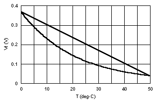
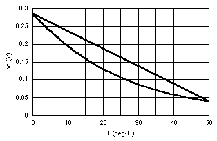
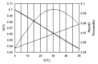
Figure 3 shows the results of the last solution, the approximate plot of Vt versus temperature for this case, with a straight line added between the end points. Notice how with this circuit, the slope of the Vt versus T curve is lower near the 50 ° C end. This means that the same error in voltage measurement creates a larger error in calculated temperature at that end.
 |
|
|
We can change this by adding another resistor to the circuit, as shown in Figure 4. Here the three wires defining the connections to the sensor from the source, Vs, and the measurement, Vt, are shown more clearly, along with the ground reference symbol at the very bottom. The parallel resistance formula [10] calculates the resistance of two resistors in parallel, like R2 and Rt (see also the spreadsheet rparall.wq1). One can substitute R1 for R and Rp for Rt in [9] to get the formula for this bridge [11].
 |
[10] ![]()
[11] ![]()
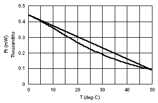
Figure 5 shows Vt (V) versus T (° C) for R1 = 806.2 kW and R2 = 5, 50 and 500 kW, from left to right, as developed in the Quattro Pro spreadsheet file, therm2.wq1. Here again, a straight line between the end points is added to the response curve Vt(T). Notice how for R2 small (1 kW) the response curve is above the linear curve and for R2 large it is below it, as in Figure 3. Also notice that for the smaller values of R2, Vt is not only smaller, but the ratio between the maximum and minimum values of Vt is smaller, 1.26, 3.05 and 7.30 from left to right. A smaller range of Vt means that the inherent measurement error of the datalogger voltage input range corresponds to a larger error in measured temperature.
 |
 |
|
|
|
 |
|
|
|
|
|
|
|
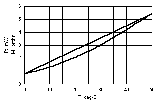
Figure 6 shows the power dissipated in the thermistor, Pt (mW), for the same circumstances. Notice that the size of R2 changes not only how large Pt can get, but where Pt is greatest. The maximum power is generated in Rt when Rt is equal to R1 and R2 in parallel. Modify and use the parallel resistor formula [10] to verify that for R2 = 50 kW, Pt is maximum when Rt is slightly greater than 50 kW.
 |
 |
|
|
|
 |
|
|
|
|
|
|
|
So, if we leave Vs at 2 V, we can adjust R1 and R2 to fix two properties of the bridge that we might find desirable. Look at the center frame in Figure 5. The plot voltage with temperature is much more linear for R2 = 50 kW than for 5 kW or 500 kW. In fact, we can see that while for the two plots on the side, Vt(T) crosses the straight line only twice, at the end points, the center plot crosses the straight line three times. We may decide that it would be desirable for the middle crossing point to occur near 25 ° C.
Now look at the ratios of Vtmax to Vtmin in Figure 5, as noted above. Not only does a value of R2 = 5 kW require a very sensitive measurement between 9.49 and 12.00 mV, the ratio between the voltages is only 1.26. Notice that the higher the voltage across the thermistor with this arrangement, the higher the voltage ratio from 0 to 50 ° C. If the full measurement span of the datalogger were 0 mV to 12.00 mV, then 9.49 mV, or over 79% of the span would be unused. Suppose the datalogger digitizes a voltage to 12 bits, or 1 part in 4096, with a digitization error of plus or minus 1 part. The error in temperature due to digitization error within the fitted span for a perfectly linear measurement would be:
[12] ![]()
This is much larger than the 0.001 ° C that we have chosen for the error due to self-heating, and a 12.00 mV measurement would be much more subject to electronic noise than a higher-voltage measurement.
So it is apparent that we want to use the largest voltage across the thermistor that we can, to avoid overly sensitive, noisy measurements and to use the most of the datalogger measurement span possible. We can calculate from [8] that for Rt = 183.766 kW at T = 0 ° C, the value of Vt at the maximum allowed Pt is Vt = (Pt*Rt)1/2 = (0.00075 (mW) * 183.766 kW)1/2 = 0.1378 V. Suppose that we have a datalogger that has input ranges of 100 mV and 200 mV, closest to this value. To avoid excessive self-heating, we choose to use the range from 0 to 0.100 V for the first trial value.
We will use the resistors, R1 and R2, to set the maximum Vt to 0.100 V, and to make the curve for Vt(T) cross the ideal linear curve at T = 25 ° C in the middle of the range. Is this the only way to design the circuit? No, but you must be very clear about what you are trying to achieve and why. Another valid goal may be to minimize the maximum value of the temperature measurement error, eT, in the range of the bridge measurement, due to all possible sources, such as digitization error, Vt(T) slope changes, and calibration fits. It may turn out in such a case that a two-point crossing of Vt with the ideal linear curve may be best. But that is a much more complicated problem than we intend to solve here.
We can use the solve-for spreadsheet feature to help us reach our design goals. In this case we set up an objective function, f, with penalties for bad results. Now import the Quattro Pro file therm3.wq1 into your spreadsheet. It is similar to therm1.wq1. Notice that the variables are in slightly different places. Find maximum Vt, max Pt, the ratio of max Vt to min Vt and the objective function, f, in cells D8, E8, D11 and G9, respectively. Let the datalogger input span, Vspan, be placed in E4, and set to 0.100 V. Look at the cell formula for f (G9). It is the sum of the penalties in G4..G8.
The first penalty, labeled Vtmax, has the formula
@IF(D9>E4,1000000*(D9-E4),1000*(E4-D9))
This is the same as saying:
[13] ![]() , forces Vt = 0.100 V
, forces Vt = 0.100 V
For the moment, let this be the only term of the objective function, f. We set the target value to 0, the formula cell to f (G9), and the variable cell to R1 (D6) or R2 (D7), the solve-for feature would change either R1 or R2 until Vt = 0.100 V to the accuracy we set for it (1e-6). When we add penalties in this approach, they must be positive and at least have a minimum near the desired value, if not a zero. We add the following penalties:
[14] ![]() , forces Vt(25 °
C) to the linear value.
, forces Vt(25 °
C) to the linear value.
[15] ![]() , forces Pt < 0.75 mW
, forces Pt < 0.75 mW
[16] ![]() , forces R1 > 0
, forces R1 > 0
[17] ![]() , forces R2 > 0
, forces R2 > 0
Now try various initial values for R1 and R2 and see what works. Alternate between choosing R1 and R2 for the variable cell, and press GO (in Quattro Pro solve-for) several times. You will notice that the solve-for feature will not always converge, and that depending on what initial values you chose, it may converge to different answers. If you put in penalties that can go negative as well as positive, you will find an even wider range of possible "solutions" as one penalty cancels out another to drive f to zero. This is to be avoided.
You may find that the objective function, f, is not very sensitive to R2, that only dV(25) in G5 is sensitive to R2. If this is the case, you can change the solve-for formula cell to G5 and the variable cell to R2 in D7. Run the solve-for several times until R2 no longer changes. Then reset the formula cell to f in G9 and try changing R1. You can also try changing the relative magnitudes of the penalties. When you are done, reset the answers for R1 and R2 to just three or four significant digits.
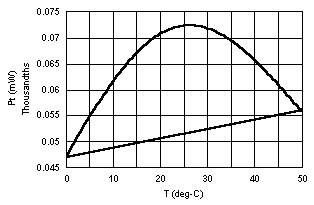
One viable answer for this circuit is R1 = 643.1 kW and R2 = 41.49 kW. Figure 7 shows the results. Notice that the maximum power dissipated, Pt, is only 0.0942 mW, well below our chosen maximum of 0.75 mW. This happens because the maximum power is dissipated in the thermistor not at 0 °C, but near 25 °C, near Rt = 50 kW instead of 183.766 kW.
 |
|
|
Look again at Figure 2. For a given value of Vs, [9] substitutes into [8] to show us [18]. Differentiating by Rt, we get [19], which shows that either a maximum or a minimum in Pt exists where Rs = Rt. It is well known that the most power is dissipated in the load, Rt, when it is equal to the source resistance, Rs. In Figure 4, the equivalent source Rs is equal to R1 and R2 in parallel, as in [10], by laws of circuit analysis that we have not discussed. Verify for yourself that this is the case, using both the equations and the spreadsheet results.
[18] ![]()
[19] 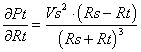
This means that we could have chosen a larger input span, Vspan, on the datalogger. Now set Vspan = 0.200 V, and try again. You should come close to R1 = 320.9701 kW and R2 = 44.25116 kW, and get a max(Pt) = 0.377 mW in E9.
Notice that the ratio of Vtmax/Vtmin in this case is about 2.75, or 0.0725 V < Vt < 0.2 V. Suppose that the datalogger we has a digital resolution of one part in 4096 with an accuracy of ± 0.05% of full scale range. On the 0.200 V scale, the accuracy would be ± 0.0001 V. Calculate the resulting errors in temperature due to digital resolution and instrument accuracy according to [12]. Assume the resolution can be expressed as ± 1/2 part and that the measurement is ideal and linear. You should have come up with the numbers ± 0.0096 °C and ± 0.0393 °C. The combined error is commonly taken as the root-sum-square (RSS) of the errors, or ± 0.040 °C. We can do nothing more about the size of this error, but we can try to see to it that the other measurement errors do not significantly raise the total RSS error.
Now change the penalty, Ptmax to:
@if(E9>=0.00075,1e+6*(E9-0.00075),1e+6*( 0.00075-E9))
This forces Ptmax toward 0.00075 mW from both directions. Set Vspan = 1.0 V (Vs = 2 V), and alternately use (R2, dV(25)) and (R1, Ptmax) for the variable cell and the formula cell, respectively. You should get close to R1 = 227.7117 kW, R2 = 46.89963 kW, max(Vt) = 0.281911 V and max(Pt) = 0.00075 mW. This shows that for Vs = 2 V, the largest possible Vspan would could use with this thermistor, and maintain Pt at 0.75 mW or less, is about 282 mV. If the datalogger has a span of 250 mV, this would work well.
There is still some latitude in choosing R1 and R2, and you should know that you can not get fixed resistors in such exact values for a reasonable cost. Resistors come in with value tolerances, that, depending on model can be from 0.1% to 20%. This means that the true resistance of an 8.2 kW resistor with a 20% tolerance can be anywhere in the range of 6.56 to 9.84 kW. Not only are the more precise resistors more expensive, but values other than "standard" 5% or 10% values are more expensive. The sequence of 5% values runs: 1.0, 1.1, 1.2, 1.3, 1.5, 1.6, 1.8, 2.0, 2.2, 2.4, 2.7, 3.0, 3.3, 3.6, 3.9, 4.3, 4.7, 5.1, 5.6, 6.2, 6.8, 7.5, 8.2, 9.1, 10. Now change R1 and R2 in at least one of the examples above to 5% values and see what you get.
Resistors are also much more stable with temperature and power dissipation than thermistors, but do change their values. Some of the most stable are the ± 1% tolerance, metal-film, military-spec RN-series, which change resistance with temperature at the rate of 0± 25 ppm (parts per million), 0± 50 ppm and 0± 100 ppm for the E, C and D suffixes, respectively. Resistors are also rated by safe power dissipation. The RN-55, RN-60 and RN-65 are typically rated at 1/8 W, 1/4 W and 1/2 W respectively (calculated via [8]). But all these specifications can change slightly from manufacturer to manufacturer.
The thermistors that you are going to use in this lab are Keystone Thermometrics model RL-0503-5820-97-MS, with the following characteristics:
The datalogger in this lab has single-ended input ranges of 0 to 2.5 mV, 7.5 mV, 25 mV, 250 mV and 2.5V. The allowable range of source voltage, Vs, is 0 to 2.5 V. Because several lab groups will be using the same source, set your design value of Vs to 2.000 V. It has a digital resolution of 1 part in 3750 and an analog accuracy of ± 1 part in 1000. Use this data, and the cook-book spreadsheets you have been given, to design a three-wire, two-resistor bridge circuit for measuring temperature from 0 to 50 °C. Don't forget to calculate b. You can use a self-heating error larger than 0.001 °C, but you must then justify your choice.
The entire class will be sharing the same assortment of 5% carbon-film resistors. It contains five each of the values (W): 2.2, 15, 22, 33, 39, 47, 51, 68, 82, 180, 270, 390, 510, 680, 820, 1.2k, 1.8k, 2.7k, 3k, 3.9k, 5.1k, 5.6k, 6.8k, 8.2k, 12k, 18k, 27k, 33k, 39k, 51k, 56k, 68k, 82k, 120k, 150k, 180k, 270k, 330k, 1.5M, 2.2M, 3.3M, and 4.7M. It contains at least ten each of the values (W): 1, 10, 100, 120, 150, 220, 330, 470, 560, 1k, 1.5k, 2.2k, 3.3k, 4.7k, 10k, 15k, 22k, 47k, 100k, 220k, 470k, 1M, and 10M. It would be best to try to use duplicate values from the 10 or more set, and save the rest for adjustment resistors to avoid shortages. The resistors are color-coded as to value. Table 1 below shows the codes, which you should memorize, if possible.
There may also be some multi-turn cermet potentiometers available, in values of 1k, 5k, 10k and 20k, which will also be in short supply. A potentiometer (pot) is a variable resistor, usually consisting of a fixed resistor with a wiper that runs along its length, like an almost infinitely divisible voltage divider circuit. These particular potentiometers are adjusted by means of a small, slotted peg that turns 10 to 15 times over the span of the pot. You can use one to adjust a bridge circuit to a desired point. Try to bring a jeweler's screwdriver, like one for tightening the earpieces on glasses, to lab. Try to have more than one design ready, in case of conflicts due to shortages.
Justify your design choices, including justification based on the resulting RSS error, and produce plots of output voltage, Vt (V), and thermistor power dissipation, Pt (mW), versus temperature, T (°C). Estimate the accuracy of the measurement due to the digital resolution and analog accuracy of the datalogger, separately and root-sum-squared, assuming that the design produces a bridge output that is linear with temperature. If you choose to design with a non-linear output that crosses the linear curve at only two points, you must show how this produces a lower maximum RSS measurement error.
|
|
|||||
|
|
|
|
|||
|
|
|
|
|
|
|
|
|
|
|
|
|
|
|
|
|
|
|
|
|
|
|
|
|
|
||
|
|
|
|
|
||
|
|
|
|
|
||
|
|
|
|
|
||
|
|
|
|
|
||
|
|
|
|
|
||
|
|
|
||||