

This is a brief and limited tutorial in the use of finite difference methods to solve problems in soil physics. It is meant for students at the graduate and undergraduate level who have at least some understanding of ordinary and partial differential equations. After an explanation of how to use finite differences in cook-book fashion, the equations, computer code and graphic results are given for three examples: heat flow, infiltration and redistribution, and contaminant transport in a steady-state flow field.
Often, for problems of heat flow, or unsaturated water flow or contaminant transport in soil, there may be no analytic solutions or neat equations describing the result. In such cases, we use numerical methods on a computer. Perhaps the simplest of the numerical methods to understand and to program are finite differences, derived from Taylor series expansions (DuChateau and Zachmann, 1989). Some methods are so simple, they can even be done in a spreadsheet. But in the interests of accuracy, we will only discuss the methods that require some ability to program in a computer language such as C, BASIC or FORTRAN. The examples here given will be in FORTRAN, but can be converted to other languages.
Because they are often confusing to the neophyte, we will not discuss Taylor series derivations. Finite differences can be explained and used in cook-book manner, if one is careful. If the reader has no other experience in these methods, he or she should keep in mind that this is a limited discussion. Such issues as stability, convergence, iteration methods, implicitness, discretization errors and non-Darcian flow will not be covered. So the reader should be careful to understand that a great deal more study is necessary to use these methods successfully in many cases. This is only a brief synopsis.
We will discuss how to numerically solve four types of problems: heat flow, transient unsaturated flow, steady-state water flow and contaminant transport in soil. The first type is one of the easiest because it only involves diffusion. It is usually linear with analytic solutions often available. The second type is extremely non-linear, with analytic solutions only available in special cases. It can be written as a diffusive problem, but if gravity flow dominates over the flow due to matric potential gradients, as in a coarse soil, it can be considered advective. The third type is perhaps the easiest because it involves no change in time. Whereas the others must be solved repeatedly by stepping through time, this problem only has to be solved once. The fourth type often depends upon the unsaturated flow, because if there is water flow due to pressure head differences, the flow solution must be obtained to put into the advective part of contaminant transport.
Consider the definition for the first ordinary or partial derivative [1a,b] of the pressure head h. Suppose that we have a pressure head, h(z,t), distributed along a grid of points, z0, z1, ..., zi-1, zi, zi+1, ..., znp-1, znp, with np segments of fixed size, Dz = (zi+1-zi), and that we want to evaluate the first partial derivative with respect to z, ¶h(z,t)/¶z, from z0 to znp. We can simply look at the definition [1b] and estimate the derivatives with [2]. This method is only an estimate. It has error components linearly related to Dz, Dz2, Dz3, and on up, but the largest component goes as the size of Dz. As Dz gets larger, so does the error of the approximation.
[1a] ![]()
[1b] ![]()
[2] 
Notice how we have changed the notation to make it more compact. If Dz is fixed over the range from z0 to znp, we can write each zi = z0+i Dz. If we have a Dt fixed over the range of interest, we can write tj=t0+j Dt. Each value of h(zi, tj) can be given in notation as hij, even if the Dz and Dt are not fixed. These values of h are called finite or discrete, because they occur, or are known, only at the discrete positions, (zi, tj), in time and space.
If we want to estimate the second partial derivative [3], we apply the difference rules as shown below. The 1/Dz in front of the difference term should be expressed as Dz = zi+1/2-zi-1/2, where the i+1/2 and i-1/2 indicate the midpoints between zi+1 to zx and zi to zi-1. If all the zi are fixed and Dz apart, then the differences between adjacent points are all Dz. If not, then 1/Dz can be expressed by 2/(zi+1-zi-1). The error of these approximations goes as the size of Dz2. Since the problems we will discuss involve only first and second partial derivatives, [2] and [3] are the two basic formulae needed. Of course, that is not all. If these are blindly applied, without a full knowledge of stability and convergence criteria, they will likely fail.
[3] 
Suppose that we want to estimate the solution of the transient heat equation [4] in the vertical direction, where the space step, Dz, and time step, Dt, are fixed. Using [2] and [3], also assuming the thermal conductivity, k, is constant in time and space, we can approximate it with the explicit finite difference formula [5]. It is called explicit because when all the discrete variables for T at the j+1 time level (i.e., tj = t0 + (j+1) Dt) are placed on the left and all the variables at the j time level are placed on the right, the solution for each Tij+1 is separate and distinct, in other words, so easy to solve that it can be done in a spreadsheet.
[4] ![]() , where T is temperature (°C or K), t is time
(s), DT is thermal diffusivity (m2/s), and
z is vertical distance, positive upwards (m).
, where T is temperature (°C or K), t is time
(s), DT is thermal diffusivity (m2/s), and
z is vertical distance, positive upwards (m).
[5] ![]()
If one knows the initial distribution of temperature, T(z,t = t0), then one has the initial values of Tij=0. One can use [5] to solve for all of the values at Tij=1, and from those the values at Tij=2, and so on. So in this notation, the values at the j time level are always the known and the values at the j+1 time level are to be solved. This method is straightforward and can be done in a spreadsheet.
Unfortunately, there are limitations on the sizes of Dt and Dz. If they are chosen wrong, method [5] becomes unstable; it simply blows up. For this reason, we will use a more difficult form [6], called an implicit method. It is unconditionally stable with all Dz and Dt. If Dz and Dt are chosen poorly or too large, it may give a bad answer, but it will not explode.
[6] ![]() , where r = (DT Dt)/Dz2
, where r = (DT Dt)/Dz2
If we gather all the terms at the j+1 time level on the left and the j time level on the right, we see what looks like three unknowns, (Ti-1,Ti,Ti+1)j+1, in one equation. Because of our use of compact notation, we actually have a large number of equations. Let i = 0 to np, where the boundary conditions are T0=T(z0) and Tnp=T(znp) for all time t > t0. That gives us equations for i = 1 to np-1, with unknown values of Tij+1 for i = 1 to np-1, making the solution possible.
[7] ![]()
Suppose that we have constant boundary conditions, T0 and Tnp. Those values are always known and go on the right hand side, producing [8] and [9]. Even if T0 and Tnp vary with time as known functions, they go to the right hand side because they are known, but to be mathematically consistent with the implicit method, they should be expressed at the j+1 time level. An example of this situation might be soil temperature that is considered to be constant at z = -2 m, but varying with time and weather at the soil surface, z = 0 m, known from datalogger measurements.
[8] ![]()
[9] ![]()
Equations [7] to [9] can be expressed as a matrix equation in linear algebra [10], multiplying an (np-1)x(np-1) matrix by an (np-1)x1 matrix to get an (np-1)x1 matrix. Notice how the boundary conditions fit on the first and last rows. Remember how in matrix multiplication a row of the matrix on the left multiplies a column of the matrix on the right of the multiplication. See how this gives back equations [7] to [9].
[10] 
In even more compact matrix notation, [10] can be expressed as [11], where the bold letters indicate the entire matrix and the exponent, -1, indicates the inverse matrix. It shows that if we have the inverse of the (np-1)x(np-1) matrix, A, we can solve for all the Tij+1 with a simple matrix multiplication.
[11] A Tj+1 = Tj --> A-1 A Tj+1 = A-1 Tj --> Tj+1 = A-1 Tj
The matrix A is called tridiagonal because it has only three diagonals of -r, (1+2r) and -r. It is called diagonally dominant because |1+2r| > |-r| + |-r|; the absolute value of each element of the diagonal is greater than the sum of the absolute values of the elements on the same row off the diagonal. This second property assures that the solution to [11] will exist. The first allows an easy solution with a well-know algorithm for solving tridiagonal systems of equations, subroutine tridia in Listing 1. If the second property is not true, then the algorithm will likely fail.
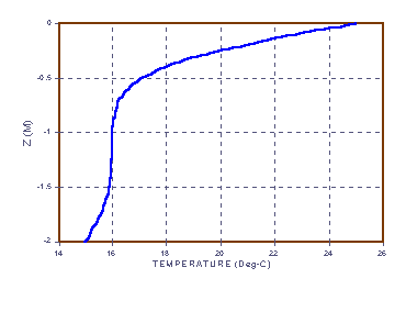
Suppose we wish to solve [12], at time tl = 24 h (or 86,400 s). Let the temperature at z = -2 m be T0 = 15 °C, the temperature at the soil surface, z = 0 m, is Tnp = 25 °C, and the initial temperature for the soil in between be 16 °C. Listing 1, FORTRAN program fdtemp.for, shows how to set up and use subroutine tridia in each time step to solve for the next set of Ti.
[12] 
(25 Jan 2000 Note: an earlier version of [12] had the IC at 18°C, an error. Anyone finding errors is welcome to point them out. See the webmaster address below.)
This program is set up to calculate 80 segments of dz = 0.025 m, for time steps of dt = 1 s, and then write out the results to file outtem.dat. It begins by initializing all the variables, using the array tmj(i) for the Tij discrete values, and tm(i) for the Tij+1 discrete values. Notice how the tridiagonal A matrix is set up in the aa(i), bb(i), and cc(i) arrays, and the Tj matrix is set up in the dd(i) array, with additions to the proper elements to account for the boundary conditions. When the subroutine tridia is called, it changes the aa, bb, and cc arrays and puts the answer for Tj+1 in the dd array. Figure 1 shows the temperature distribution in the soil 24 hours after the initial conditions. Notice how the boundary temperature conditions have diffused into the soil from the ends.
 |
|
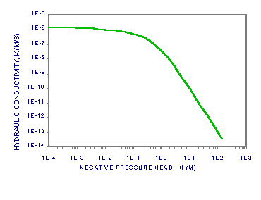
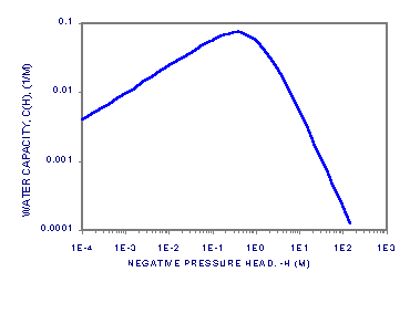
Now suppose that we want to solve the equation for unsaturated flow [13]. Let the water content, q, be dependent on the water pressure head, h, according to [14]. Let the hydraulic conductivity, K, be a product of the saturated conductivity, Ks, and the relative conductivity, Kr(h), be dependent h according to [15]. Let the soil be a Glendale clay loam (Kirkland, et al., 1989), with qr = 0.1060, f = 0.4686, a = 1.04 1/m, n = 1.3954 and Ks = 1.5162 m/s. We will also need c(h) = ¶q/¶h [16], where we add 10-20 to the function to aid in the numerical solution, which can be sensitive to values of c(h) = 0. Figures 2a-c show plots of q, Se, K and c(h) for the soil to about h = -15 bar, the nominal pressure for immobile water in the pores.
[13] ![]() , where q is water content
(m3-water/m3-soil), t is time (s), z is
space, positive upwards (m), K is hydraulic conductivity (m/s),
H is water total head (m), where H = h+z, h is water pressure
head (m) and z is also water gravity potential head (m).
, where q is water content
(m3-water/m3-soil), t is time (s), z is
space, positive upwards (m), K is hydraulic conductivity (m/s),
H is water total head (m), where H = h+z, h is water pressure
head (m) and z is also water gravity potential head (m).
[14]  , where f is porosity (m3/m3),
h is pressure head, qr is
residual water content (m3/m3), a
is fitting parameter (1/m), and m and n are also fitting parameters.
[15]  , where Ks is the saturated hydraulic conductivity
(m/s), Kr is the relative unsaturated hydraulic conducitivty (m/s),
Se is the effective saturation (dimensionless) and m is the fitting
parameter from [14].
[16]  , where c(h) is the water capacity (1/m).
 |
 |
|
|
 |
|
|
|
In one of the simplest approaches, [16] and the definition of total head, H, are applied to [13] to get [17]. We apply the ordinary finite difference rules to get [18], where Kim is the mean conductivity between the grid points at zi and zi-1, and Kip is the mean conductivity between the grid points at zi+1and zi. Since K is a function of Se and Se is a function of h, we know the K(zi) = Ki from hi. But we need an average of the values of Ki-1 and Ki, Kim, to calculate flow from Darcy's law between zi-1 and zi. We will use the arithmetic means, Kim = (Ki-1+Ki)/2 and Kip = (Ki+Ki+1)/2, because they are the easiest. Like many easy means, they produce valid Darcian flow only in special cases (Baker, 1995b, 1998), but if the space steps, Dz, are small enough, so are the errors.
[17] ![]()
[18] 
Notice that the j and j+1 time levels are only given to the pressure head, h, in [18]. Because of the simple time-stepping method we use here, all the other variables, ci and Ki, are taken from the values of hij, at the j time level. This is called lagging the coefficients. In a truly implicit solution, they would all be taken from the j+1 time level. The only way to do that numerically is to repeatedly calculate the time step, called iteration, each time recalculating the values of ci and Ki with the updated values of hij+1 until solution converges to a fixed limit.
If one does this, then using [17] is no longer the best way. Equation [18], called the head-based approach, is known to produce mass balance errors. In other words, the change in water content, both by cell and by profile, does not match the net inflow. The modified Picard method (Celia, et al., 1990) solves [13] to an arbitrarily small mass balance error by what is essentially a Newton's iteration for a system of equations. In this method the water capacity, c, is used, but only as a matrix component in the "slope" of [13], called the Jacobian matrix, used to balance the equation. It's worth learning.
Equation [18] may be rearranged to get [19], defining the tridiagonal system of equations away from the boundary conditions. In this case, we will assume that the bottom boundary at z0 is a constant pressure head, h0, producing the difference equation [20].
[19] ![]() ,
,
where rzz = Dt/Dz2 and rz = Dt/Dz.
[20] i=0: ![]()
errata (15 Feb 2007): I seem to have mistakenly changed h(sub i+1, super j+1) in [19] to h (sub i-1, super j+1) in [20]. My thanks to Prof. Tahar Loulou, Université de Bretagne Sud, Lorient Cedex, France.
The infiltration flow at the upper boundary condition requires special treatment. We usually consider that the grid points, zi, are centered in grid cells, and that the mean flow between two grid points zi and zi+1, qi+1/2, is centered somewhere between, on the boundary between the cells. If the space steps, Dz, are uniform, we center qi+1/2 halfway between. So, in order to put the infiltration, qinf, at the soil surface, one approach shifts the coordinate system up by Dz/2 from that of the temperature flow example and puts the soil surface at znp-(Dz/2). This does not change the finite difference equations, but changes our interpretation of where they solve.
The Mass Balance equation [21] shows how this approach works. We replace only the flow between znp-1 and znp-2 with Darcy's law, leaving the soil surface flow intact. So, when we make the proper substitutions into the general equation [19] for the top boundary, we get [22]. Note that in our coordinate system, all flows are positive upwards, so the infiltration flow, qinf, must be negative during rain, and positive for ET.
[21] 
[22] i=np-1: ![]()
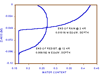
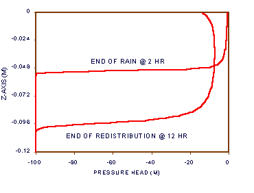
Let us suppose a rain of 0.5cm/h for two hours (qinf = -1.389(10-6) m/s), into a very dry soil at h = -100 m head, followed by ET of 0.02cm/h (qinf = +0.05556(10-6) m/s) for ten hours after the rain (on one of the three cloudy days per year in New Mexico). Since the rate of rain is less than Ks, we will assume that all of the rain infiltrates into the soil. Since at h = -100 m, K is below 10-13 m/s, we will neglect the flow out the bottom of the profile, and consider the bottom boundary condition to be constant head, as in [20]. Let np = 100, Dz = 0.002 m, and Dt = 10 s.
Figures 3a-b show the water content and head distributions after the rain and after the additional ten hours of redistribution under ET and drainage. Listing 2 shows the model code of program fdflow.for. Notice that if 0.5 cm/h of rain infiltrates for two hours, the equivalent water depth added to the soil should be 1.0 cm. After ten hours, an ET at 0.02 cm/h, shoud remove 0.2 cm, leaving 0.8 cm. Notice that the numbers from the model are 1.016 cm and 0.8182 cm, errors of +1.6% and +2.275%, respectively, calculated from [23].
[23] water added to profile = ![]()
 |
 |
|
|
As noted before, this method suffers from mass balance errors, but that is not the only source. The time step is called first-order accurate in time, because as the time step increases, one component of the error increases proportionally to Dt. The finite difference approximation for the second partial derivative of h with respect to z is second-order accurate in space, proportional to Dz2. The first partial of K with respect to z can of course only be first-order accurate in space. These are called time and space step discretization errors. They can only be reduced by taking smaller steps at the expense of much longer model run times on the computer, or by using higher-order steps, such as Runge-Kutta time steps (Baker, 1995a). There is a common misunderstanding that the modified Picard method reduces time step discretization error, but this is not the case.
Also for larger space steps, particularly in the vertical, such standard means as the arithmetic, geometric, harmonic and upstream can produce severe non-Darcian flow (Warrick, 1991). This kind of implicit difference model operates under an inherent assumption that flow is constant over the space step between grid points and over the time step between time points. The accumulated net mass change is added back into the profile at the end of the time step by the computer. Under these assumptions, a constant flow according to Darcy's law requires a particular interblock conductivity mean, related to the unsaturated conductivity relation and the size of the vertical space step. Only rarely does this Darican mean correspond to standard means. The only saving grace in using standard means is that for small enough space steps, where the adjacent Ki approach each other, all means must become equal in that limit.
Unfortunately the math is too involved to discuss here. The point is that just because the math looks reasonable and the curves (Figures 3a-b) look good, the answer can never be assumed to be perfect. As one the best teachers in this field said, "Just because you got the answer you wanted, it doesn't mean it's any good." The results of these highly nonlinear problems are often counterintuitive.
We will combine the last two topics of this section, steady-state flow and solute transport, in the next example. Suppose, using the soil of the last example, that we have the opposite situation, a shallow water table with constant evaporation (no transpiration), with salt concentrating in the soil surface. Constant evaporation will create a constant, steady-state flow from the water table, which we assume to be a virtually infinite source of water and salt. This is not the usual physical situation, but it allows us to introduce other solution techniques.
First, the steady-state flow has to be determined, then the solute transport which depends upon the flow. If the flow were not steady, it would have to be solved to obtain the pore-water velocities at each time step before transport could be solved. Using steady-state flow allows us to use just one set of pore water velocities for the whole transport solution.
For the steady-state problem, let us assume that the water table is always at depth, z0 = -zl (m), the soil surface is a znp = 0, and that the evaporation, qe (m/s), is always one-half the possible evaporation, the hydraulic conductivity of the soil surface, Knp (m/s). Notice in this case that we have placed the last grip point, znp, exactly at the soil surface. If flow is steady, then water content does not change, the left-hand side of [13] and [21] is zero [24], and q = qe from the water table up, because ¶q/¶z = 0.
[24] ![]()
We assume constant Dz = zl/np. Equation [24] converts in finite difference form to [25], from which we have dropped the 1/Dz2 term as common. Kim and Kip (m/s) are again the arithmetic means introduced in [18]. The total head, H (m), is still H = h+z, where h is the pressure head (m) and z is the elevation head (m). By definition, h = 0 at the water table, z = -zl, therefore H0 = H(zl) = -zl, giving the boundary condition [26].
[25] 
[26] i=1: ![]()
This time at the soil surface we will use the ghost point method to define a constant flow boundary. We pretend that the soil extends another Dz above znp to a point with total head, Hnp+1. This allows us to define the evaporation flow, qe, by [27], which gives us the ghost point boundary condition [28]. Notice that we assume that Knp is the mean conductivity from znp-1 to znp+1, and that we define qe = ae Knp, where 0<ae<1. This method allows us to have both the flow, qe, and the head, Hnp, at znp. Applied to [25], this produces [29], where Kip = (Knp+K(hnp+1))/2, and hnp+1= hnp-1 - 2 Dz (1 + ae).
[27] ![]()
[28] ![]()
[29] i=np: 
Equations [25], [26] and [29] define another tridiagonal system of equations that can be solved by lagging the coefficients, Ki. This time we must provide a starting estimate of the solution and iterate the solution until [24] is true thoughout the profile on a grid point by grid point basis. For the starting solution, we use hydrostatic conditions, where Hi = -zl, i = 0 to np. We then calculate the flow between each pair of points [30], and iterate until the condition [31] is met. For this problem, it takes about 5 or 6 iterations.
[30] ![]()
[31] ![]()
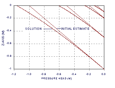
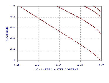
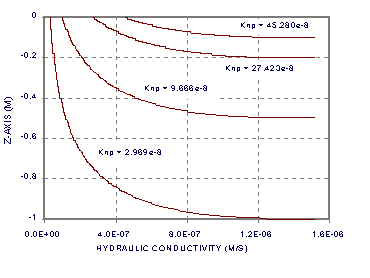
Figures 4a, b and c, show the solutions for ae = 0.5, np = 500 and zl = 1, 0.5, 0.2, and 0.1 m. The bottom of each curve is at the water table, and the top at the soil surface. The pressure head profiles (5a) show both the hydrostatic initial estimate (straight line) and the final solution. Notice how the final solution diverges from hydrostatic condition with increasing z. Notice in Figure 4b how although the flow is constant and the soil is homogeneous, the water content, q, changes steadily with z. Figure 4c also contains notation identifying the value of Knp (m/s) at the soil surface. The first part of Listing 3 of program fdtrns.for contains the FORTRAN code used to generate these solutions (but as a separate program).
 |
 |
|
|
 |
|
|
|
Now let us consider the solute transport problem [32], where q is volumetric water content, as before, Cl is solute concentration in solution (kg/m3-solution), (q Cl) is solute concentration in the soil (kg/m3-soil), t is time (s), z is space, positive upwards (m), v-bar is the mean pore-water velocity between grid points (m/s), De is the effective combined molecular and mechanical dispersion of the solute in the pore water (m2/s), zl is the distance from the soil surface to the water table (m), as before, and tl is the end time of the problem (s).
[32] 
For this problem, let q times v-bar be qe, the steady-state flux determined from solving [24]. Let De = 2(10-10) m/s, Co = 0.1 kg/m3, zl = 0.1 m, and tl = 36000 s (ten hours). We naturally keep the same grid system using zi from z0 = -zl to znp = 0, where np = 500. Notice from Figure 4b that although q does not vary much from z = -0.1 m to z = 0, it can vary significantly if the water table is lower. If it does, then one cannot pull q out of [32] as a common factor that is constant with z.
The single-step, non-iterated finite difference method we used for temperature and transient unsaturated flow only works for a partial differential equation expressed in a single dependent variable. We could extract q from inside the partial differentiations by treating it as a coefficient that can be averaged, like the conductivity means Kim and Kip. Instead, let us keep it with Cl by using the transformation variable, u = q Cl (or Cl = u/q), producing [33]. This may produce a more accurate solution.
[33] 
Because the first term on the right hand side of [33] is driven by the mass flow of the soil water, it is called the advection term. The other is, of course, the diffusion term. Consider which values we must pick in the finite difference method for advection, a first partial derivative, because it does not fit as neatly into a tridiagonal system of equations as does the second-order diffusion term. Let the flow from zi to zi+1 be called vi = qe/q. Since flow is normally defined between the grid points and q and u on the grid points, what q and u do we use? If vi is positive, as we know that qe is in this case, then mass can only be transfered from zi to zi+1, from upstream. If vi is negative, it can only go the other way. So, let us use the method in Table 1 to approximate the advection term in [33] in finite differences, where vi = qe/qi. If we average the product (q De) as we did K in [29], we get [34]-[37].
|
|
||
|
|
|
|
|
|
|
|
|
|
|
|
|
|
|
|
|
|
|
|
[34] 
where (q De)im = De (qi-1 + qi)/2, (q De)ip= De (qi + qi+1)/2, rz = Dt/Dz and rzz = Dt/Dz2
[35] or  and
and
[36] i=1:  , constant source boundary
[37] i=np: 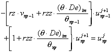 , no flow boundary
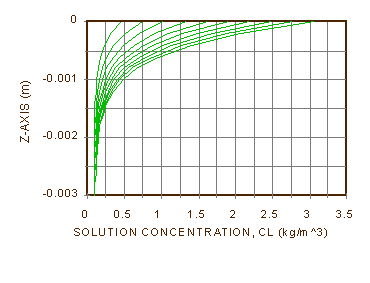
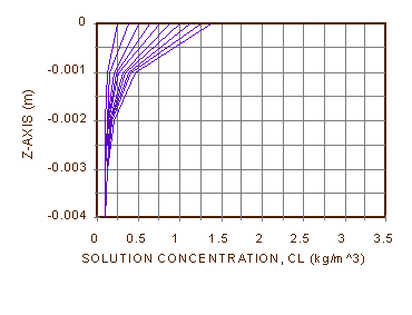
Figure 5a shows the results of [34]-[37] for np = 500 and dt = 10 s, plotted at one-hour intervals up to tl, ten hours. Figure 5b shows the same results for np = 100. The character of the solution is a growing exponential. The average concentration of solute in the top 1 mm of soil at ten hours is about 13.8 times the initial concentration, or the concentration of the source at the water table. We can see why if we consider the profile at infinite time, when the concentration gradient of solute to the surface has become so large that downward diffusion balances upward advection [38], and there is no more change in concentration with time. In other words, ¶Cl/¶t = 0, and we can also drop a common ¶/¶z from [32]. Notice that for qe = 2.264(10-7) m/s, q = 0.4623, De = 2(10-10), zl = 0.1m and z = 0, Cl/Co = e244.9 = 10106.3. This is a huge number. The salt in solution will come out of solution and form a crust on the soil long before this comes to pass, also demonstrating that we did not take that into account in formulating this problem.
 |
 |
|
|
[38] ![]()
What of the differences we see in Figure 5b? They point out that we have not adequately discussed many aspects of numerical modeling, such as discretization error, dissipation, dispersion, convergence, and stability. In this case, the difference is probably due to the space step discretization error. For advection, it is proportional to the size of Dz times the first partial derivative of Cl with respect to z, plus other terms. For diffusion, it is proportional to Dz2 times the second partial derivative of Cl with respect to z, plus other terms. An exponential solution in z can provide a lot of large derivatives, making the numerical solution very sensitive to the size of Dz. We have no assurance at this point even of the accuracy of Figure 5a. It is often wise to check the accuracy of a numerical solution by running it again with smaller time and space steps.
This concludes the discussion of numerical methods to solve problems in Soil Physics. It may be reasonable to use the ones presented here in cook-book fashion, provided that the problem parameters and conditions do not stray too far from those above. But the reader is warned that a firm grounding in these methods usually requires a course in numerical methods, a course in partial differential equations, and a course in either finite differences or finite elements, not to mention the necessary background in differential and integral calculus required for them. And that is just the beginning ...
Baker, D.L., 1995a, Applying higher order DIRK time steps to the "modified Picard" method, GROUND WATER 33(2):259-263.
Baker, D.L. 1995b, Darcian weighted interblock conductivity means for vertical unsaturated flow, GROUND WATER 33(3):385-390.
Baker, D.L. 1998, Developing Darcian means in application to Topopah Spring welded volcanic tuff, Report DOE/ER/82329-2 to the U.S. Department of Energy under Award No. DE-FG02-97ER82329, 118p.
Celia, M.A., E.T. Bouloutas and R.L. Zarba, 1990, A general mass-conservative numerical solution for the unsaturated flow equation, Water Resour. Res. 26(7):1483-1496.
DuChateau, P. and D. Zachmann, 1989, Applied Partial Differential Equations, Harper and Row, New York, ISBN 0-06-041772-2, 620p
Kirkland, M.R., R.G. Hills and P.J. Wierenga, 1992, Algorithms for Solving Richards' Equation for Variably Saturated Soils, Water Resour. Res. 28(8):2049-2058.